5 Common Mistakes Beginners Make With Arduino Projects
Diving into the world of DIY electronics can be quite daunting and overwhelming. There's the matter of picking the right components to use, learning the hand tools, and understanding the software. Thankfully, Arduino projects can ease you into electronics and programming. These nifty microcontroller boards have been around for a couple of years now, but they continue to be one of the go-to platforms for most hobbyists and makers, especially when it comes to developing beginner-friendly projects.
While Arduinos are relatively easy to use for newbies, they still come with a learning curve like any other tool. As you start practicing connecting components and creating sketches, you're bound to make some mistakes along the way. Some of these mistakes are manageable and easy to fix, but others can cost you your board. So before you go ahead and get started with Arduino, it's wise to be familiar with these errors first so you can avoid them.
Using the wrong power supply
In the early stages of your learning process, you won't need to worry much about how to supply power to your board. Most beginner-friendly projects can be conveniently powered by simply connecting the Arduino board to your computer, so picking an external power supply isn't a concern just yet. However, if you do come to the point where your project requires one, always make sure your supply has the right power rating suited for your type of Arduino board.
The recommended input for most Arduino models when powered via non-USB means is 7 to 12V, with a limit of 20V. It's always a good idea to read the specification sheet, though, just to make sure. This is especially true when you're buying Arduino clones: Sometimes, they don't replicate the exact technical attributes of the genuine Arduinos, so always go back to the spec sheet to confirm.
When you use the incorrect voltage rating, it can lead to problems with your board and circuit. A voltage lower than the required rating might not be enough to produce 5V and 3.3V at the power pins. On the other hand, using a voltage higher than necessary can harm your board and potentially kill it.
In addition to choosing the right voltage rating, it's important to ensure that you connect the external power supply to the Arduino the right way. This shouldn't be a problem when you're using the USB connection with a power bank or standard charger. But if you're connecting to the VIN pin, take note of the supply's polarity: Positive of the supply to be connected to VIN, and negative to GND. There's no reverse polarity protection on this pin, so a wrong connection can cause serious damage to your board.
Not using a resistor
Resistors may be small and cheap, but they're far from being a minor component in your circuit. In fact, they actually serve two major roles: protecting your components from too much current, and making sure your component works as intended. The first purpose is typically found in any circuit that uses LEDs. Without a resistor, LEDs tend to shine too brightly, overheat, and potentially blow up if left for an extended duration. You also need resistors to protect other electronic components, such as buzzers, transistors, and motors.
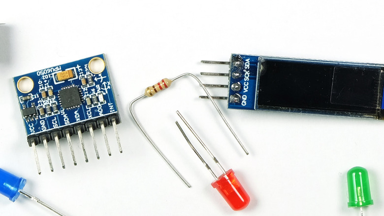
Aside from offering protection, resistors are also used to make sure that your input components function as expected. In such cases, the resistors (typically 10K Ohm with a resistor color code of brown-black-orange) are known as either pull-up or pull-down. A pull-up resistor connects your input directly to a positive voltage (5V or 3.3V). This keeps the input signal HIGH when the component is inactive, and switches it to LOW when you do trigger it. Conversely, a pull-down resistor directs your input to GND, making its default signal LOW, and sending a HIGH signal when the input is activated. If you don't use any pull-up or pull-down resistors, your pin's signal will randomly fluctuate due to interference and cause your circuit to misbehave.
Likely the only time you won't need to worry about resistors is when using sensor modules. Since they're essentially designed to be plug-and-play, most of them already come with all necessary components built in. However, if you're still unsure, you can always check the module's datasheet. SparkFun or Adafruit also includes specific example tutorials, complete with wirings and code, that demonstrate how to use the sensor modules with your Arduino board.
Unintentionally shorting the board or circuit
The fastest way to kill your Arduino board or make one, if not all, of your pins/components blow is by unintentionally shorting something in the board or circuit. Shorts happen when two pins that shouldn't be connected come into contact with each other.
There are a number of ways you can accidentally create a short. One is by connecting any of the power pins to the GND, consequently shutting down your board and even potentially killing it. While this may seem like a pretty obvious and easy mistake to avoid, it typically happens when wiring your connections on a breadboard. You may have unwittingly placed your 5V input and GND on the same line, effectively shorting the two pins. That's why it's important to familiarize yourself with how a breadboard works before you even start using it.
You can also produce a short in a circuit even when you're not using a breadboard. For instance, if you solder your LEDs, resistors, sensors, and other whatnot with a wire, and don't properly insulate the pins with heat-shrink tubing or electrical tape, they might end up touching other pins. You'll also face the same dilemma when soldering pin headers to boards. With the small space between the headers, it's easy to accidentally solder them together. It's best to practice using the soldering iron and desoldering pump with cheap printed circuit boards first if you're still not comfortable with these tools.
Another common cause of shorts is leaving conductive materials, such as stray jumper wires, precision screwdrivers, or solder droplets lying around your board. These materials can mistakenly connect two or more pins, so always ensure that your board and circuit are free of such debris before connecting a power supply to your Arduino project.
Code issues

So you already have your circuit set up and the Arduino sketch uploaded, but nothing seems to be working. More often than not, the issue lies in the code. This is particularly common while you're still getting the hang of programming nuances, but nothing a quick review won't fix. Some of the frequent oversights in the sketch include the following:
- A missing semicolon or curly brace: It's important to end your lines with a semicolon wherever appropriate, and double-check whether your curly braces are by pairs. Otherwise, you'll run into a compiler error. If this error message is unclear, it's probably because you're missing a semicolon or curly brace somewhere.
- Adding a semicolon to #include and #define: These two elements don't use semicolons unlike most of the other elements.
- Using the wrong I/O pin: To get the expected results, make sure the pin specified in the code is the same pin your component is connected to.
- Calling digitalRead() or analogRead() on an unconnected pin: This will generate randomly fluctuating values, messing up how your program operates. Always ensure that the circuit connection matches your program.
- Using the wrong duration in delay(): This element measures time in milliseconds, not seconds. If you need a 10-second delay, multiply it by 1000, and don't simply use delay(10).
- Assigning the wrong data type to a value: For instance, if you assign int to a value with a decimal, it won't produce a decimal number as you may expect. This will only leave you with the whole number.
- Using the wrong baud rate: In Serial communication, baud rates in the code and the device you're talking to need to match in order to establish proper communication.
If you're unsure about the syntax of your code, always consult the Arduino Language Reference.
Misuse of special I/O pins
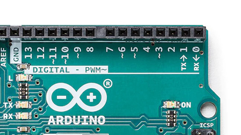
The thing about Arduino's I/O pins is that they come with special functions (and corresponding limitations) that beginners are generally unaware of. For instance, in the Uno board, pins D0 and D1 can be used as standard digital pins where you can connect common components like LEDs, ultrasonic sensors, and motors. However, they also double as Serial pins (RX on D0 and TX on D1) that enable the board to communicate with your computer.
Unfortunately, the pins can only be used for one function at a time, so that means that when you're communicating with the computer — such as when printing data to the Serial monitor with Serial.print() — you can no longer use D0 and D1 as standard digital pins. If, however, you don't have any Serial elements in the code, you can use these pins for whatever digital purpose you need. Remember, you still have to disconnect the components every time you upload a new code (which is a process that essentially communicates with the computer). Otherwise, your components would be in conflict with the Serial communication, and the sketch upload can fail.
Another common I/O pin misuse among beginners is using pins A4 and A5 on the Uno as regular analog input pins while also having an I2C device connected to the SCL and SDA pins (the unlabeled pins next to AREF on the Uno board). While there are physically four pins, they're actually connected internally (SDA to A4 and SCL to A5). That said, you can't use them at the same time. If you need to use an I2C device with more than four analog components, it's best to switch to a different board with more analog pins, such as a Nano or a Mega.